Zhejiang Motorbacs Technology Co., Ltd.
  •   Language
  • Home
  • Products+
  • About+
    • Company Profile
    • Service & Support
    • FAQs
  • Capabilities+
    • Our Facilities
    • Quality Control
  • R&D
  • Cases
  • Videos
  • Contact
  • R&D
R&D
Establishment of the Motorbacs Technology Center

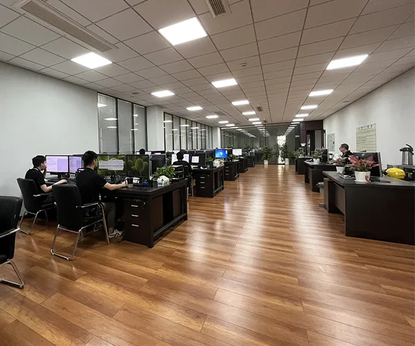
The Modo Technology Center was established in April 2022 and currently consists of more than 80 professionals. It is organized into two major divisions: the Project Department and the Engineering Technology Department.

The Project Department includes the Project Review Section, New Project Development Section, Mass Production Project Section, and Supplier Development Section. The Engineering Technology Department comprises the Modeling & Analysis Section, Tooling & Mold Technology Section, Tooling & Fixture Section, Production Line Planning Section, Manufacturing Engineering Section, Process Implementation & Standard Cost Section, and Testing & Laboratory Section.

The Technology Center integrates multiple core functions, including product design, simulation, and prototype development; tooling design, simulation, and manufacturing; production line design, simulation, and implementation; new project development; mass production project management; project monitoring; cost management; and resource development. It acts as a comprehensive innovation hub and serves as a primary engine for ongoing development and advancement.

  • Design Capability
  • Design Capability
  • Design Capability
  • Design Capability
Design Capability

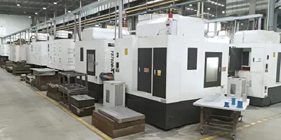
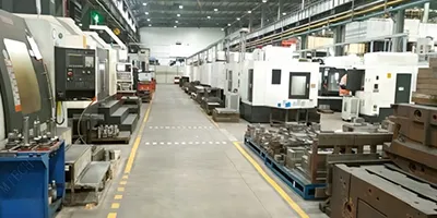
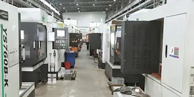
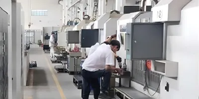
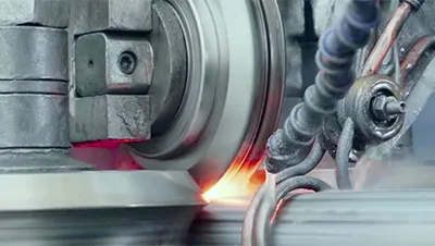
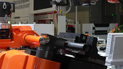
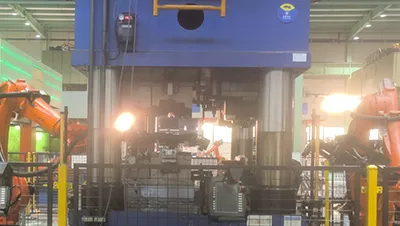
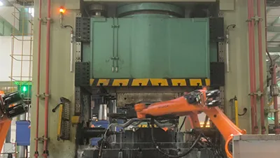
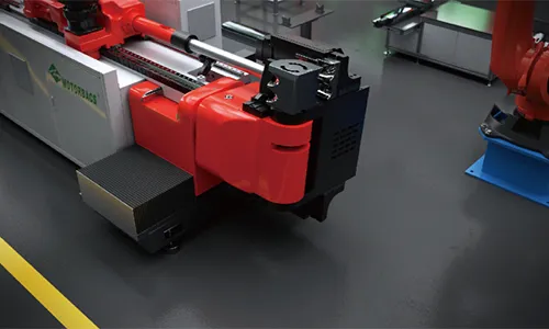
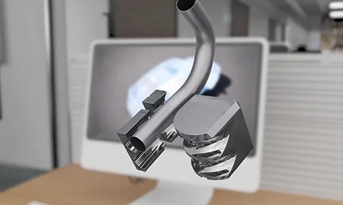
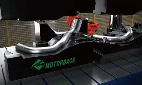
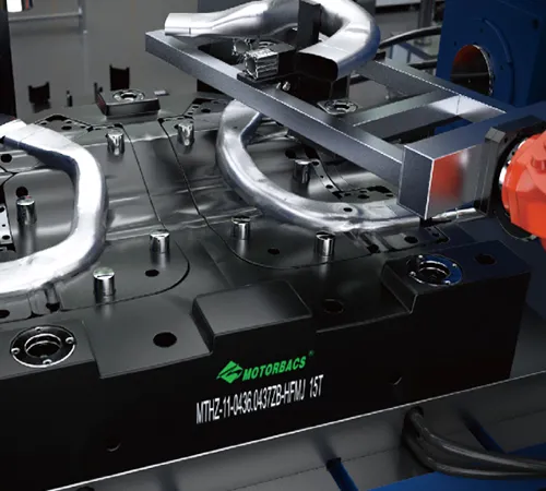
We have an experienced team of professional tooling and checking fixture design engineers. To date, more than two hundred sets of molds and checking fixtures have been designed for chassis torsion beam and trailing arm projects. The team is proficient in CAE analysis, 3D modeling software, and advanced surface design technologies. Current in-house tooling manufacturing capability includes three gantry machining centers, two high-speed milling machining centers, twenty-four vertical machining centers, four CNC lathes, and three wire-cutting machines. With these resources, all tooling and fixture processing and manufacturing work can be completed internally, with the exception of heat treatment and five-axis machining.

Product Development: Hydroforming
  • Welded tubeWelded tube
  • Tube bending Tube bending
  • PreformingPreforming
  • HydroformingHydroforming
  • Laser cuttingLaser cutting
  • InspectionInspection
Hydroforming CAE Analysis
  • Hydroforming CAE Analysis
  • Hydroforming CAE Analysis
  • Hydroforming CAE Analysis

The production process for high-strength and lightweight automotive chassis tubular beams includes welded tube manufacturing, tube bending, preforming, internal high-pressure (hydroforming), laser cutting, and final inspection. Each stage follows strict and independent technical specifications. With more than ten years of accumulated technical experience, a complete set of core technologies with independent intellectual property rights has been developed and established.

  • Hydroforming Mold CAE Strength and Durability Analysis
  • Mold deformation is approximately 0.13 mm when the internal forming pressure reaches 250 MPa
  • Under 250 MPa internal forming pressure, the maximum mold stress reaches approximately 720 MPa
  • The actual yield strength of the mold material must be greater than 1.5 × 720 MPa to ensure safety margin and service life
Welding Forming CAE Analysis
  • Hydroforming CAE Analysis
  • Hydroforming CAE Analysis
  • Hydroforming CAE Analysis
  • Pipe Welding Capacity
  • Yield Strength ≤1000MPa
  • Material Thickness ≤6mm
  • Pipe Diameter ≤140mm
  • Diameter Tolerance ±0.15mm
  • Length Tolerance ±0.25mm
Welded Tube Inspection
Performance & Metallographic - Testing of Welded Pipes
Performance Testing

Performance Testing - Flattening / Flaring Tests

  • Company standard for flattening: distance between compression plates after flattening < 2T + 1 mm;
  • National standard requirement: distance between plates = 1/3 of the pipe outer diameter.
  • Under both standards, the welded seam must show no cracks, tears, or weld failure to be qualified.
  • For the flaring test, a 200–300 mm section is taken, and a 180° flanging test is performed using a special mold.
  • No tearing or cracking at the weld seam during outward flanging of the pipe wall.
Metallographic

Metallographic - Fusion Line

  • Fusion Line Width Requirements
    Japan (Nippon Steel): 0.02–0.20 mm
    Germany: 0.02–0.12 mm
    Korea PSP: 0.05–0.30 mm
  • Company Control Standard
    Fusion line width controlled within 0.02–0.11 mm
    Observed under 100× microscope
  • Metallographic
  • Metallographic

Metallographic - Streamline Angle

  • Streamline Angle Requirements
    Japan (Nippon Steel): 40°–70°
    Germany: Inner Wall: 60°; Outer Wall: 65°; Difference ≤ 10°
  • Company Control Standard
    Streamline angle at weld zone controlled within 50°–70°
Bending Technology
Bending Process

Bending Process

  • Angle: 13-axis full-servo tube bending ensures angular accuracy of 0.05° and feeding accuracy of 0.05 mm.
  • Circularity: Multi-mandrel support with synchronized lubrication during bending ensures stable circularity.
  • Thinning: Coordinated control of bending, assist pushing, and mandrel feed, combined with push-feed compensation and synchronized lubrication; thinning rate ≤ 10% under 1.5D conditions.
  • Forming: Three-dimensional angular and dimensional contour accuracy is controlled within ±0.5 mm.
Processing Capability

Processing Capability

  • Yield strength >350 MPa to ≤980 MPa
  • Material thickness >1.0 mm to ≤6.0 mm
  • Outer diameter >30 mm to ≤127 mm
  • Thinning rate <10%.
Pre-forming

Pre-forming

  • Diameter change: Nominal diameter change ≤ −1 mm
  • Forming contour: When placed onto the hydroforming mold profile, deviation ≤ 0.4 mm
  • Position accuracy: Pipe end positional accuracy controlled within ±0.5 mm, ensuring consistent hydroforming feed position
  • Thinning: Lubrication is applied during pressing to ensure material flow, preventing negative impact on wall thickness and providing favorable conditions for thinning control during hydroforming
Hydroforming

Hydroforming

  • Forming feeding precision
    Feeding displacement accuracy: 0.01 mm
    Working feed accuracy: 0.02 mm
  • In-line pressure precision
    Synchronization time difference between feeding and internal pressure: 0.002 s
  • In-die punching accuracy
    Punching timing response relative to pressure and feeding axis: 0.002 s
    Aperture accuracy: ≤ 0.2 mm
    Hole pitch accuracy: ≤ 0.4 mm
  • Part forming accuracy
    Profile accuracy: ≤ 0.4 mm
    Thinning rate: < 15%
Laser Cutting

Laser Cutting

  • Dual-channel control enables 24-hour continuous laser processing
  • Repeat positioning accuracy of each axis: ±0.02 mm
  • Maximum running speed of each axis: 120 m/min
  • Maximum acceleration of each axis: 1G
  • 16-axis full-servo control, with 6-axis synchronized linkage during laser processing
  • Supports online and offline machining motion simulation
  • High response, high efficiency, and high-power laser processing capability
Contact us for more information or to request a quote
Talk to our experts
  • Automotive Chassis Parts
  • Metal Tube Processing Equipment
    1. Hydroformed Subframe Components
    2. Hydroformed Subframe Components Hydroformed tubular components for automotive subframes and chassis systems More info
    1. Hydroformed Frame Rails & Crossmembers for BOF
    2. Hydroformed Frame Rails & Crossmembers for BOF Hydroformed chassis components for body-on-frame chassis systems in off-road and heavy-load applications More info
    1. CDC Damper Tubes
    2. CDC Damper Tubes Precision tubular components for CDC (Continuous Damping Control) dampers in automotive suspension applications More info
    1. Air Spring Aluminum Component
    2. Air Spring Aluminum Component Precision aluminum pistons and housings for automotive air spring systems More info
    1. CNC Tube Bending Machine
    2. CNC Tube Bending Machine
    1. CNC Tube Hydroforming Press
    2. CNC Tube Hydroforming Press
    1. Double-Station 3D Laser Cutting Machine
    2. Double-Station 3D Laser Cutting Machine
    1. Laser Tube Welding Line (Pipe & Tube Mills)
    2. Laser Tube Welding Line (Pipe & Tube Mills)
Zhejiang Motorbacs Technology Co., Ltd.
admin@motorbacs.com
motorbacs@gmail.com
+86-15726800888
Metal Tube Processing Equipment
  • CNC Tube Bending Machine
  • CNC Tube Hydroforming Press
  • Double-Station 3D Laser Cutting Machine
  • Laser Tube Welding Line (Pipe & Tube Mills)
  • Laser Scanning 3D Inspection Equipment
  • CNC Milling Machine
Automotive Chassis Parts
  • Hydroformed Subframe Components
  • Hydroformed Frame Rails & Crossmembers for BOF
  • CDC Damper Tubes
  • Air Spring Aluminum Component
  • Metal Bellows Accumulator
  • Metal Tubes for Automotive Engines
Quick Links
  • Company Profile
  • Our Facilities
  • Quality Control
  • Service & Support
  • FAQs